Wifi経由でArduinoスケッチをマイコンに書き込む [OTA/ESP-WROOM-02]
OTA(Over The Air)と呼ばれる無線通信(Wifi)を経由してESP-WROOM-02のマイコンボードに「Arduinoスケッチ」を書き込む方法です。
次の写真はOTAでスケッチを書き込んで、LEDを点滅させています。
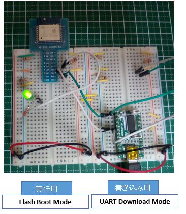
※初回は右側の書き込み用配線で「OTA用の設定」を書き込みます。
※OTAによる書き込みは左側の実行用配線で書き込みます。
配線図
LEDを点滅させる為に「実行用配線」に「IO5 - LED - 抵抗 - GND」を繋いだだけです。詳細の配線図は前述した関連記事をご覧ください。
事前準備
OTAの実行役の2.7系のPython(パイソン)をインストールします。
Windowsならば「Windows x86 MSI installer」(32bit)または「Windows x86-64 MSI installer」(64bit)をダウンロードして実行します。
注意点としては、次の画面で「Add python.exe to Path」(python.exeをパスに追加する)をクリックして「Will be installed on local hard drive」(ローカルハードドライブにインストールする)を選択します。
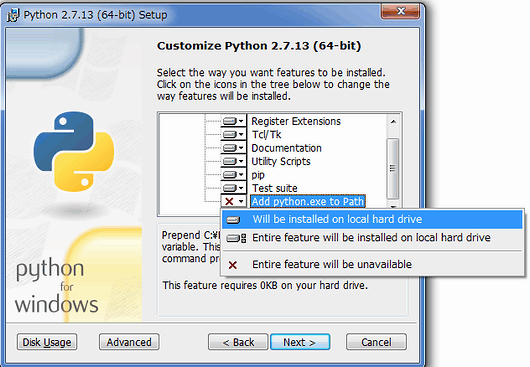
これは「python.exe」を環境変数に追加する設定です。
そして、インストールが完了したらWindowsを再起動します。
書き込みの概要
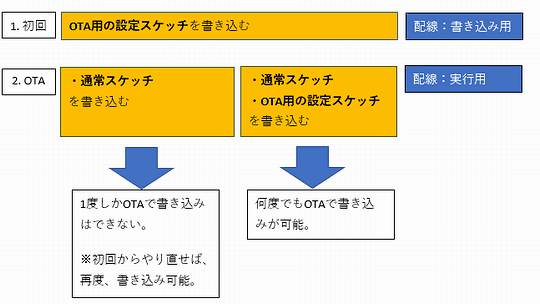
初回はUSBシリアル変換を使用して書き込み配線で「OTA用の設定スケッチ」を書き込みます。
2回目以降はOTA(Wifi経由)で「通常スケッチ」または「通常スケッチ+OTA用の設定スケッチ」を書き込みます。配線は実行用です。
2回目以降のスケッチに「OTA用の設定スケッチ」がない場合は、OTAでの書き込みはできなくなります。ある場合は、OTAでの書き込みは可能です。
※ない場合でも、初回からやり直せば、再度、OTAで書き込み可能です。
ボードの設定
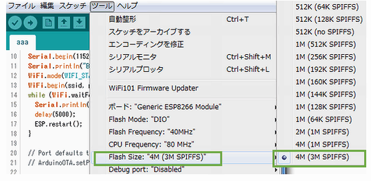
ボードは「初回/OTA」の両方とも「Generic ESP8266 Module」で「Flash Size」は「4M(3M SPIFFS)」を選択して下さい。
スケッチ1 - OTA用の設定スケッチ
初回の「OTA用の設定スケッチ」はIDEのメニューの[ファイル][スケッチ例][ArduinoOTA][BasicOTA]です。SSID、パスワードを各自の環境に合わせてください。
#include <ESP8266WiFi.h>
#include <ESP8266mDNS.h>
#include <WiFiUdp.h>
#include <ArduinoOTA.h>

const char* ssid = "xxx";
const char* password = "xxx";

void setup() {
  Serial.begin(115200);
  Serial.println("Booting");
  WiFi.mode(WIFI_STA);
  WiFi.begin(ssid, password);
  while (WiFi.waitForConnectResult() != WL_CONNECTED) {
    Serial.println("Connection Failed! Rebooting...");
    delay(5000);
    ESP.restart();
  }

  // Port defaults to 8266
  // ArduinoOTA.setPort(8266);

  // Hostname defaults to esp8266-[ChipID]
  // ArduinoOTA.setHostname("myesp8266");

  // No authentication by default
  // ArduinoOTA.setPassword((const char *)"123");

  ArduinoOTA.onStart([]() {
    Serial.println("Start");
  });
  ArduinoOTA.onEnd([]() {
    Serial.println("\nEnd");
  });
  ArduinoOTA.onProgress([](unsigned int progress, unsigned int total) {
    Serial.printf("Progress: %u%%\r", (progress / (total / 100)));
  });
  ArduinoOTA.onError([](ota_error_t error) {
    Serial.printf("Error[%u]: ", error);
    if (error == OTA_AUTH_ERROR) Serial.println("Auth Failed");
    else if (error == OTA_BEGIN_ERROR) Serial.println("Begin Failed");
    else if (error == OTA_CONNECT_ERROR) Serial.println("Connect Failed");
    else if (error == OTA_RECEIVE_ERROR) Serial.println("Receive Failed");
    else if (error == OTA_END_ERROR) Serial.println("End Failed");
  });
  ArduinoOTA.begin();
  Serial.println("Ready");
  Serial.print("IP address: ");
  Serial.println(WiFi.localIP());
}

void loop() {
  ArduinoOTA.handle();
}
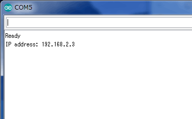
書き込む前にIDEでシリアルモニターを表示すると、書き込み後には次のように表示されると思います。※IPアドレスをメモしておきます。
書き込みが終わったら、USB電源を落としてからESP-WROOM-02を実行用配線に移動して実行させます。
そして、ESP-WROOM-02がWifi接続後にArduino IDEを再起動します。
スケッチ2 - LEDを点滅させる
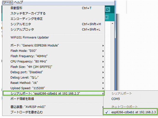
先ほど、メモしたIPアドレスを元に「シリアルポート」を選択します。
次のコードはOTAで書き込みするスケッチです。内容はLEDを1秒毎に点滅させます。(OTA用の設定スケッチも含まれています。)
#include <ESP8266WiFi.h>
#include <ESP8266mDNS.h>
#include <WiFiUdp.h>
#include <ArduinoOTA.h>

const char* ssid = "xxx";
const char* password = "xxx";

void setup() {
  Serial.begin(115200);
  Serial.println("Booting");
  WiFi.mode(WIFI_STA);
  WiFi.begin(ssid, password);
  while (WiFi.waitForConnectResult() != WL_CONNECTED) {
    Serial.println("Connection Failed! Rebooting...");
    delay(5000);
    ESP.restart();
  }

  // Port defaults to 8266
  // ArduinoOTA.setPort(8266);

  // Hostname defaults to esp8266-[ChipID]
  // ArduinoOTA.setHostname("myesp8266");

  // No authentication by default
  // ArduinoOTA.setPassword((const char *)"123");

  ArduinoOTA.onStart([]() {
    Serial.println("Start");
  });
  ArduinoOTA.onEnd([]() {
    Serial.println("\nEnd");
  });
  ArduinoOTA.onProgress([](unsigned int progress, unsigned int total) {
    Serial.printf("Progress: %u%%\r", (progress / (total / 100)));
  });
  ArduinoOTA.onError([](ota_error_t error) {
    Serial.printf("Error[%u]: ", error);
    if (error == OTA_AUTH_ERROR) Serial.println("Auth Failed");
    else if (error == OTA_BEGIN_ERROR) Serial.println("Begin Failed");
    else if (error == OTA_CONNECT_ERROR) Serial.println("Connect Failed");
    else if (error == OTA_RECEIVE_ERROR) Serial.println("Receive Failed");
    else if (error == OTA_END_ERROR) Serial.println("End Failed");
  });
  ArduinoOTA.begin();
  Serial.println("Ready");
  Serial.print("IP address: ");
  Serial.println(WiFi.localIP());

  // 追加コード
  pinMode(5, OUTPUT);
}

void loop() {
  ArduinoOTA.handle();

  // 追加コード
  digitalWrite(5, HIGH);
  delay(1000);
  digitalWrite(5, LOW);
  delay(1000);
}
「OTA用の設定スケッチ」の部分を削除すれば、次回はOTAで書き込みができなくなります。用途によって使い分けてください。
[ERROR]: No response from device
Arduino IDEでOTAのスケッチをコンパイル、書き込み時にこのようなエラーが発生した場合は「ウイルス対策ソフト/ファイアウォール」が原因の一つです。「python.exe」に許可を与えてください。
それでも、OTAによるスケッチの書き込みが出来ない場合は、IDEのメニューの[ツール]の「Generic ESP8266 Module」のFlash Sizeが「4M(3M SPIFFS))」になっているかを確認して下さい。デフォルトの「512K (64K SPIFFS)」になっている場合は、そのままでは書き込みが出来ませんのでご注意下さい。
最後に
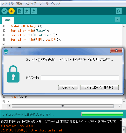
デフォルトではOTAの書き込み認証はありません。サンプルコード内にあるArduinoOTA.setPassword()にパスワードを設定すると、それがそのまま認証パスワードとなります。
以上となります。
掲示板
ArduinoやRaspberry Piなどの電子工作の掲示板を作成しました。質問やわからない事は電子工作 (Arduino・ラズパイ等)でユーザー同士で情報を共有して下さい。
関連記事

プチモンテ ※この記事を書いた人
 | |
| 💻 ITスキル・経験 サーバー構築からWebアプリケーション開発。IoTをはじめとする電子工作、ロボット、人工知能やスマホ/OSアプリまで分野問わず経験。 画像処理/音声処理/アニメーション、3Dゲーム、会計ソフト、PDF作成/編集、逆アセンブラ、EXE/DLLファイルの書き換えなどのアプリを公開。詳しくは自己紹介へ |
| 🎵 音楽制作 BGMは楽器(音源)さえあれば、何でも制作可能。歌モノは主にロック、バラード、ポップスを制作。歌詞は抒情詩、抒情的な楽曲が多い。楽曲制作は🔰2023年12月中旬 ~ | |